
品牌
*注:按产品型号,可检索常见问答、样本、证书等信息。

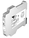
The Inverse Isolation Amplifier DEB 6250 is used for isolation and conversion of bipolar and unipolar industrial signals with inverse characteristic.
-
Easy realization of inverse transmission characteristic
Inverse characteristic for unipolar and bipolar signals can be easily set by using DIP switch -
Universal power supply for 20...253 V AC/DC
Applicable world-wide for all common supply voltages -
3-port isolation
Protection against erroneous measurements due to parasitic voltages or ground loops -
Ultra small sized housing
12.5 mm housing with plug-in screw terminal blocks -
High bandwidth; high accuracy
No distortion; no falsification of measured signal -
Protective Separation
Protects service personnel and downstream devices against impermissibly high voltage -
Maximum reliability
No maintenance costs -
5 Years Warranty
Defects occurring within 5 years from delivery date shall be remedied free of charge at our plant (carriage and insurance paid by sender)
The Inverse Isolation Amplifier DEB 6250 is used for isolation and conversion of bipolar and unipolar industrial signals with inverse characteristic.
Due to the easy selection of the input and output ranges, the new universal power supply and the ultra-small housing the Isolation Amplifier is suitable for flexible use. High reliability and Protective Separation are further characteristics that make the DB 6250 unrivaled.
The order key allows you to select the desired input and output ranges to which the unit will be adjusted at the factory before delivery. These can be easily reconfigured at any time by means of DIP switch settings. Subsequent readjustment or measured range compensation can then be performed at the zero/scan potentiometers on the front panel. Also the cut-off frequency can be adapted to the measurement task by using the DIP Switch.
The small housing with 12.5 mm width saves space in your switch cabinet and facilitates by the practical plug-in screw terminal blocks the assembly. For range setting a simple housing unblocking is installed which makes it possible to reach easily all control elements on the mounting rail.
The new universal power pack for 20 ... 253 V AC/DC means the DB 6250 can be used anywhere in the world, with all mains power supplies. The unit’s high efficiency contributes significantly to reducing the unit’s own heat generation. This is reflected in extremely high reliability and long-term stability. A green LED on the front of the unit has been provided to monitor the power supply.
Input
| Voltage | Current | |
|
Input signals 1) (terminal/switch selectable) |
± 10 V, 0...10 V, 2...10 V ± 5 V, 0...5 V, 1...5 V |
± 20 mA, 0...20 mA, 4...20 mA ± 10 mA, 0...10 mA, 2...10 mA |
| Input resistance | Approx. 1 MOhm | Approx. 25 Ohm |
| Input capacitance | Approx. 1 nF | Approx. 1 nF |
| Overload |
Voltage limitation via 30 V Z-Diode, max. continuous current 30 mA |
≤ 200 mA |
Output
| Voltage | Current | |
|
Output signals, inverse characteristic (switch selectable) 1) |
± 10 V, 0...10 V, 2...10 V ± 5 V, 0...5 V, 1...5 V |
± 20 mA, 0...20 mA, 4...20 mA ± 10 mA, 0...10 mA, 2...10 mA |
| Load | ≤ 10 mA (1 kOhm bei 10 V) | ≤ 12 V (600 Ohm bei 20 mA) |
| Linear transmission range | unipolar: –2 ... +110 %, bipolar: –110 ... +110 % | |
| Ripple | < 10 mVrms | |
General Data
| Transmission error | 0,1 % of final value | |
| Temperature coefficient 2) | 100 ppm/K final value | |
| Zero/Span compensation | ± 10 % | |
| Cut-off frequency (-3 dB) | > 10 kHz 1), switchable to < 30 Hz | |
| Test voltage |
4 kV, 50 Hz Input against output against power supply |
|
|
Working voltage 3) (Basic Insulation) |
Up to 1000 V AC/DC for overvoltage category II and pollution degree 2 acc. to EN 61010-1 between all circuits. | |
| Protection against electrical shock 3) | Protective separation according to EN 61140 by reinforced insulation in accordance with EN 61010-1 up to 600 V AC/DC for overvoltage category II and pollution degree 2 between all circuits. | |
| Ambient temperature |
Operation Transport and storage |
–20 °C to +70 °C –35 °C to +85 °C |
| Power supply | 20 ... 253 V AC/DC, |
AC 48 ... 62 Hz, approx. 2 VA DC approx. 1.0 W |
| EMC 4) | EN 61326 -1 | |
| Construction | 12.5 mm housing, protection type: IP 20 | |
| Weight | Approx. 100 g | |
- Factory setting , if no other information is given by ordering
- Average TC in specified operating temperature range
-
As far as relevant the standards and rules mentioned above are considered by development and production of our devices. In addition relevant assembly rules are to be considered by installation of our devices
in other equipments. For applications with high working voltages, take measures to prevent accidental contact and make sure that there is sufficient distance or insulation between adjacent situated devices. - Minor deviations possible during interference
Terminal assignments
Wire cross-section max. 2.5 mm², Multi-wire connection max. 1 mm² (two wires with same cross-section)
| 1 | Input + current | 5 | Output + |
| 2 | Input - current | 6 | Output - |
| 3 | Input + voltage | 7 | Power supply ~ |
| 4 | Input - voltage | 8 | Power supply ~ |
Product line
| Device | Order No. | ||||
| Inverse Isolation Amplifier | DEB 6250 AG - | XX - | XX | ||
|
(Factory default setting, reconfigurable any time by using DIP-switch) |
Input | ± 10 V | 00 | ||
| 0 ... 10 V | 01 | ||||
| 2 ... 10 V | 02 | ||||
| ± 5 V | 03 | ||||
| 0 ... 5 V | 04 | ||||
| 1 ... 5 V | 05 | ||||
| ± 20 mA | 06 | ||||
| 0 ... 20 mA | 07 | ||||
| 4 ... 20 mA | 08 | ||||
| ± 10 mA | 09 | ||||
| 0 ... 10 mA | 10 | ||||
| 2 ... 10 mA | 11 | ||||
| Output | ± 10 V | 00 | |||
| 0 ... 10 V | 01 | ||||
| 2 ... 10 V | 02 | ||||
| ± 5 V | 03 | ||||
| 0 ... 5 V | 04 | ||||
| 1 ... 5 V | 05 | ||||
| ± 20 mA | 06 | ||||
| 0 ... 20 mA | 07 | ||||
| 4 ... 20 mA | 08 | ||||
| ± 10 mA | 09 | ||||
| 0 ... 10 mA | 10 | ||||
| 2 ... 10 mA | 11 | ||||
|
Example: Inverse Isolation Amplifier, Input ± 5 V, Output 4 ... 20 mA |
DEB 6250 AG - |
03 - |
08 |
||
|
If no information is given by ordering, the devices are delivered with the standard configuration: Input signal ±10 V, Output signal ±10 V. |
|||||


