
品牌
*注:按产品型号,可检索常见问答、样本、证书等信息。

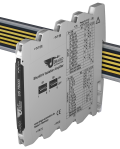
Shunt / mV Isolation Amplifier DES 75000
Isolation and Conversion of Bipolar and Unipolar mV-Signals
The Isolation Amplifier DES 75000 is used for separation and conversion of bipolar and unipolar mV-signals such as those frequently used for current measuring with shunt resistors or other applications with low sensor voltages.
-
Calibrated signal setting
Input and output range can be set by using DIP switch – high precision without any further adjustment -
Switchable Zero/Span compensation
For readjustment of the shunt/mV signal or measuring section -
3-Port isolation
Protection against erroneous measurements due to parasitic voltages or ground loops -
Extremely slim design
6.2 mm slim housing for a simple and space saving DIN rail mounting -
Optional In-Rail-Bus mounting rail connector
allows for fast and economical installation -
Protective Separation acc. to EN 61140
Protects service personnel and downstream devices against impermissibly high voltage -
5 Years Warranty
Defects occurring within 5 years from delivery date shall be remedied free of charge at our plant (carriage and insurance paid by sender)
The Isolation Amplifier DS 75000 is used for separation and conversion of bipolar and unipolar mV-signals such as those frequently used for current measuring with shunt resistors or other applications with low sensor voltages.
The input and output range of DS 75000 can be easily set by using DIP switch. Due to the calibrated range selection no further adjustment is necessary.
A switchable compensation of the measuring range can be performed at the Zero/Span potentiometers on the front panel. Also the cut-off frequency can be adapted to the measurement task by using the DIP Switch.
The auxiliary power can be supplied via the connection terminals or via the optional In- Rail-Bus connector. A green LED on the front of the unit has been provided to monitor the power supply.
Technical Data
Input
|
Input signal (switch selectable) |
± 60 mV, ± 100 mV, ± 150 mV, ± 250 mV, ± 300 mV, ± 500 mV 0 to 60 mV, 0 to 100 mV, 0 to 150 mV, 0 to 250 mV, 0 to 300 mV, 0 to 500 mV |
| Input resistance | ≥ 100 kOhm |
| Overload | ≤ 30 V |
Output
| Voltage | Current | |
|
Output signal (switch selectable) |
± 10 V, 0 to 10 V, 2 to 10 V ± 5 V, 0 to 5 V, 1 to 5 V |
± 20 mA, 0 to 20 mA, 4 to 20 mA ± 10 mA, 0 to 10 mA, 2 to 10 mA |
| Load | ≤ 5 mA (2 kOhm at 10 V) | ≤ 12 V (600 Ohm at 20 mA) |
| Linear transmission range | unipolar: –1 to +110 %, bipolar: –110 to +110 % | |
| Ripple | < 10 mVrms | |
General Data
| Transmission error | < 0.1 % full scale | |
| Temperature coefficient 1) | < 100 ppm/K | |
| Zero/Span compensation | ± 5 % of measuring range | |
|
Cut-off frequency -3 dB (switchable ) |
8 kHz, 100 Hz | |
| Response time T99 | 100 µs, 7 ms | |
| Test voltage |
3 kV AC, 50 Hz, 1 min Input against output against power supply |
|
|
Working voltage 2) (Basic Insulation) |
Up to 600 V AC/DC for overvoltage category II and pollution degree 2 acc. to EN 61010-1 between all circuits. | |
| Protection against electrical shock 2) | Protective separation according to EN 61140 by reinforced insulation in accordance with EN 61010-1 up to 300 V AC/DC for overvoltage category II and pollution degree 2 between all circuits. | |
| Ambient temperature |
Operation Transport and storage |
–25 °C to +70 °C (-13 to +158 °F) –40 °C to +85 °C (-40 to +185 °F) |
| Power supply | 24 V DC 16.8 V to 31.2 V, approx. 0.8 W | |
| EMC 3) | EN 61326-1 | |
| Construction | 6.2 mm housing, protection class: IP 20, mounting on 35 mm DIN rail acc. to EN 60715 | |
| Weight | Approx. 70 g | |
- Average TC based on the final value in specified operating temperature range
- As far as relevant the standards and rules mentioned above are considered by development and production of our devices. In addition relevant assembly rules are to be considered by installation of our devices in other equipments. For applications with high working voltages, take measures to prevent accidental contact and make sure that there is sufficient distance or insulation between adjacent situated devices.
- Minor deviations possible during interference
Block diagram

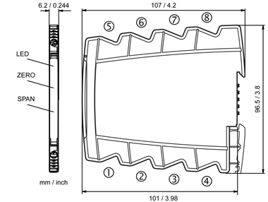
Dimensions
Connection
Captive plus-minus clamp screws
Wire cross-section max. 2.5 mm² / AWG 14
Stripped length 6 to 8 mm / 0.28 in
Screw terminal torque 0.8 Nm / 7 lbf in
Optional power connection via In-Rail-Bus (see accessories)
Terminal assignments
| 1 | + | Input |
| 2 | - | Input |
| 3 | n.c. | |
| 4 | n.c. | |
| 5 | + | Output |
| 6 | - | Output |
| 7 | + | Power supply (connected to In-Rail-Bus) |
| 8 | - | Power supply (connected to In-Rail-Bus) |
Product line
| Devices | Order No. |
| Shunt / mV Isolation Amplifier, calibrated range selection | DES 75000 S |
| Shunt / mV Isolation Amplifier, calibrated range selection, In-Rail-Bus for power supply | DES 75000 B |


