
品牌
*注:按产品型号,可检索常见问答、样本、证书等信息。

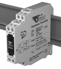
Resistance Transmitter DER 41
Measuring of Resistors with Fixed Setting
The Resistance Transmitter DER 41 converts the sensor resistance value to a standard signal and makes it galvanic isolated available on output.
-
Cost optimized resistance measuring
in 2-, 3- and 4-wire sensor connection -
Only 60 mm installation depth, 11.2 mm wide
Can be installed in economical standard terminal boxes -
Fixed ranges, easy to use
Ready to use without any settings or adjustments -
Zero/Span compensation on front panel
for readjustment of sensor and measuring equipment or line compensation at 2-wire sensor connection -
True 3-port separation
Protection against erroneous measurements due to parasitic voltages or ground loops -
Protective Separation acc. to EN 61140
Protects service personnel and downstream devices against impermissibly high voltage -
Unlimited use with 24 V AC/DC power supply
Universally applicable for all measurement and industrial applications -
5 Years Warranty
Defects occurring within 5 years from delivery date shall be remedied free of charge at our plant (carriage and insurance paid by sender)
The Resistance Transmitter DER 41 converts the sensor resistance value to a standard signal and makes it galvanic isolated available on output.
For applications where one measuring range only is used, the Resistance Transmitters DR 41 offers a cost-effective alternative.
A cross-connector for the auxiliary power supply ensures fast and easy installation. The slim housing with 11.2 mm width saves significant space on the DIN-rail. If required a measuring range compensation can be performed at the Zero/Scan potentiometers behind the front cover.
Analog signal processing guarantees precise measured values with short response times and outstanding signal reproduction at the output.
Protective Separation and the 24 V AC/DC power supply make the DR 41 universally applicable for all measurement and industrial applications, as well as for building automation.
Technical Data
Input
| Measuring range | Fixed ranges within 20 Ohm to 1 MOhm, see product line |
| Sensor connection | 2-wire, 3-wire, 4-wire sensor connection, see product line |
| Sensor wire resistance | < 25 Ohm / wire, maximum 5 % of final value at 2-wire connection |
| Sensor current | 0.1 μA to 5 mA, depends on measuring range |
Output
| Output signal |
0 to 20 mA, 4 to 20 mA, 0 to 5 V, 1 to 5 V, 0 to 10 V, 2 to 10 V see product line |
|
| Load |
Current output Voltage output |
≤ 500 Ohm ≥ 2 kOhm |
| Ripple | < 10 mVrma | |
General Data
| Transmission error | < 0.2 % full scale | |
| Temperature coefficient 1) | < 0.025 %/K | |
| Zero/Span compensation | ± 5 % | |
| Response time T99 | < 2 ms | |
| Test voltage | 3 kV AC, 50 Hz, 1 min., input against output against power supply | |
|
Working voltage 2) (Basic Insulation) |
Up to 600 V AC/DC for overvoltage category II and pollution degree 2 acc. to EN 61010-1 | |
| Protection against electrical shock 2) | Protective separation according to EN 61140 by reinforced insulation in accordance with EN61010-1 up to 300 V AC/DC for overvoltage category II and pollution degree 2 between all circuits. | |
| Ambient temperature |
Operation Transport and storage |
–20 °C to +60 °C (–4 °F to +140 °F) –35 °C to +85 °C (–31 °F to +185 °F) |
| Power supply | 24 V AC/DC, ± 15 % |
AC: 48 to 62 Hz, approx. 2 VA DC: approx. 0.7 W |
| EMC 3) | EN 61326 -1 | |
| Construction | 11.2 mm housing, protection class: IP 20 | |
| Weight | Approx. 50 g | |
- Average TC in specified operating temperature range.
- As far as relevant the standards and rules mentioned above are considered by development and production of our devices. In addition relevant assembly rules are to be considered by installation of our devices in other equipments. For applications with high working voltages, take measures to prevent accidental contact and make sure that there is sufficient distance or insulation between adjacent situated devices.
- Minor deviations possible during interference.
Block diagram
Dimensions
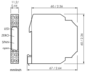
Terminal assignments
Wire cross-section max. 2.5 mm²
| 1 | Input R | 5 | Output + |
| 2 | Input R | 6 | Output - |
| 3 | Input 3-wire | 7 | Power supply ~ |
| 4 | Input 4-wire | 8 | Power supply ~ |
Product line
| Device | Sensor connection | Order No. | ||
|
Resistance Transmitter |
2-wire connection 3-wire connection 4-wire connection |
DER 41 P - 2 DER 41 P - 3 DER 41 P - 4 |
X X X |
X X X |
| Input | 0 to 20 Ohm | 2 | ||
| 0 to 50 Ohm | 3 | |||
| 0 to 100 Ohm | 4 | |||
| 0 to 200 Ohm | 5 | |||
| 0 to 500 Ohm | 6 | |||
| 0 to 1000 Ohm | 7 | |||
| 0 to 2000 Ohm | 8 | |||
| 0 to 5000 Ohm | 9 | |||
| 0 to 10 kOhm | A | |||
| 0 to 20 kOhm | B | |||
| 0 to 50 kOhm | C | |||
| 0 to 100 kOhm | D | |||
| 0 to 200 kOhm | E | |||
| 0 to 500 kOhm | F | |||
| 0 to 1 MOhm | G | |||
| Output | 0 to 20 mA | 2 | ||
| 4 to 20 mA | 4 | |||
| 0 to 5 V | 5 | |||
| 1 to 5 V | 8 | |||
| 0 to 10 V | 6 | |||
| 2 to 10 V | 7 | |||
|
Cross-connector (2 pcs) |
for looping through the power supply for up to 10 units, splittable |
DZU 0801 |
||
广泛运用于石油、化工、冶金、天然气、制药、煤矿、船舶、建材等行业


